How to Build Your Own AIS Receiver: A Step-by-Step Guide to Tracking Marine Vessels
AIS guide: how to assemble an AIS receiver with your own hands
Introduction
Just ten to fifteen years ago, receiving radio signals from sea vessels was the prerogative of large companies and professionals with expensive equipment. However, with the development of digital technologies and the advent of affordable SDR (Software Defined Radio) devices, the ability to receive and decode automatic identification system (AIS) signals has become available to a wide audience, including radio amateurs and technical enthusiasts.
We are a team developing an international service for vessel tracking in real time. At the current stage, we have implemented our first own AIS signal reception point using available components, third-party programs and open solutions. This is our first practical experience, which we want to share with those who are interested in the topic of marine radio communications, independent reception and processing of signals.
The purpose of this material is to provide a clear and accessible technical guide: from theory and selection of equipment to practical setup and signal reception. We hope that it will be useful and will be passed on to the community of people interested in receiving radio signals, navigation and marine sphere. In the future, we plan to develop this area and work on creating our own modular receiving stations, but for now, we are sharing the first developments and steps that can already be reproduced.
What is AIS and how does signal reception work
AIS (Automatic Identification System) is an automatic identification system used by ships to transmit navigational information. It operates on VHF frequencies (Very High Frequency) and was developed to improve the safety of navigation, allowing the exchange of data between ships and shore services. AIS is prescribed by the International Maritime Organization (IMO) to ensure the safety of navigation.
The AIS transmitter on a ship (especially if it is a class A vessel) must be turned on at all times. Of course, there are cases when AIS transmitters are deliberately switched off, as a rule, they are associated with illegal activities of various kinds (although recently not only with it, but this is already quite extensive material and requires a separate article).
When the vessel is far out in the ocean, the signal from the AIS transmitter is received by satellites. When the vessel is quite close to the shore (usually 20 nautical miles, but sometimes further, depending on the height of the antenna), the AIS signal can be received using a shore station, the prototype of which we will explain in this article.
What data is transmitted via AIS:
unique vessel identifier (MMSI)
vessel name, its type and flag
vessel IMO and its call sign
current coordinates (latitude, longitude)
way and speed
dimensions, deadweight and other technical parameters
destination port, etc.
This data is updated from a few seconds to several minutes, hours or days, depending on many factors (including whether the transmitter is turned off). AIS signals are transmitted on open frequencies and can be received by any receiver tuned to the appropriate ranges.
The main AIS frequencies are:
AIS 1: 161.975 MHz (channel 87B)
AIS 2: 162.025 MHz (channel 88B)
How to assemble a shore-based AIS receiver
A very simple diagram of the operation of a shore-based AIS station is shown in Figure 1
Fig. 1. Scheme of operation of a coastal AIS station, generated by OpenAi
To assemble a shore-based AIS receiver, you will need the following:
an antenna tuned to the VHF range (optimally, a 162 MHz marine antenna)
coaxial cable (with minimal losses)
RTL-SDR (USB dongle based on the RTL2832U chip)
software for receiving a radio signal
audio signal transmission software
software for demodulating and decoding AIS data
data visualization software or service
For beginner radio enthusiasts, all of the above may sound a bit complicated, so we will tell you step by step what equipment and software we used, with examples and images. Perhaps this will make it easier to understand the process, which is actually not at all complicated, and opens up huge opportunities in the world of marine communications, even if you are on the shore.
How we assembled a coastal station-AIS
Antenna
Fig. 2. Diagram of the dependence of the antenna length on frequency
The diagram above shows roughly how long the antenna should be for each frequency. The rule - to buy the longest one and everything will be fine - does not work. When assembling the antenna yourself, you also need to take into account some other parameters, such as the plan, polarization, etc. There are many diagrams and instructions on the Internet for making simple VHF antennas, including quarter-wave ones. However, we decided not to waste time on self-assembly and ordered a ready-made one - Shakespeare 5215 VHF Sailboat Whip Antenna. This is a 3-foot (approximately 91 cm) stainless steel antenna, designed for installation on the masts of yachts and sailboats. It has proven itself excellent for receiving AIS signals, due to its good gain and robust construction.
In general, if you want to save money or just like to do craftwork, you can assemble the antenna yourself, having basic radio engineering skills and an understanding of the principles of antenna matching, using the instructions. However, if your goal is to save time, take something high quality, proven and focus on other stages of launching the station, take the option indicated above or similar to it.
Cable
To connect the antenna to the receiving module, we used a 5-meter RG316 coaxial cable with PL259 (UHF Male) / SO239 (UHF Female) connectors on one end and RP-SMA / SMA on the other. This cable was selected for several reasons: it has a suitable wave impedance (50 Ohm), which is critical for effective signal transmission without losses, and is compatible with the devices used without the need for additional adapters.
Before this, we tested thicker cables, but they had a different impedance, different from the antenna and receiver, which led to significant signal losses and incorrect operation of the system. The RG316, with its compactness and flexibility, proved itself excellent for our tasks.
Fig. 4. RG316 cable, image from AliExpress
RTL-SDR Receiver
SDR is a software-controlled radio. In a regular radio, you turn various "physical things" to catch the desired frequency. SDR allows you to send numbers to the microchip, and the chip itself changes frequencies. The accuracy of reception depends on the quality of the chip.
As a signal receiver, we used the RTL-SDR - a compact USB dongle New Generation RTL-2832 SDR with a reception range from 25 MHz to 1760 MHz and a built-in TCXO (temperature-stabilized oscillator) with an accuracy of 0.5 PPM. This is an affordable and popular solution for beginner radio amateurs and enthusiasts, allowing you to receive a wide range of signals, including AIS. The dongle (popularly known as a "whistle") is easily connected to a computer via USB and is compatible with many programs.
Fig. 5. New Generation RTL-2832 SDR USB dongle, image from Alibaba
Important: the device heats up quite a lot, and in hot weather under excessive load it can even burn out. High temperatures affect reception, so we strongly recommend working with the equipment in a well-ventilated place or even try to use a primitive passive cooling system - for example, place it on a metal surface that dissipates heat.
As for the software that accompanies this device - all disks/drivers that are sent by sellers can be thrown in the trash, so you will need the SDR# program and the amateur Zadig driver. Driver installation instructions are here
Software for receiving a radio signal
Here and below, we carried out the algorithm of actions for the software for Windows.
For receiving and initially decoding the radio signal, we used the SDRSharp program (often also written SDR#) - one of the most popular free solutions in the amateur radio community. This is a lightweight and powerful software for Windows that allows you to connect SDR receivers (including those based on RTL2832U) and work with various radio ranges.
The program allows you to:
visualize the radio spectrum in real time;
precisely adjust the reception frequency (in our case, to the frequencies of AIS channels: 161.975 MHz and 162.025 MHz);
control the bandwidth, gain and other reception parameters;
send the signal to other programs using a virtual audio cable.
When you have assembled everything up to this point, you should hear at least local FM radio stations. This will mean that the whistle and the program are working. A good sign.
Audio signal transmission program
To transmit the output audio signal from SDRSharp to the AIS message decoder program, we used VB-Audio Cable, a free virtual audio cable that creates a "bridge" between the two programs for Windows.
Functionality:
creates a virtual audio device that can be selected as an output in one program (SDRSharp) and an input in another (ShipPlotter or other software);
does not distort the signal and avoids losses typical of a physical connection via an external sound card;
works stably even with prolonged use and minimal settings.
The program is free for the basic version and is available on the developer's website VB-Audio Software at the link
After installing the program in the system sound settings, you will need to set VB-Audio Virtual Cable Input/Output in the corresponding sections, as shown in Figures 7 and 8. In the SDR# program, respectively, in the right column in the Audio section in Output, you need to select Cable Input VB-Audio, as shown in Figure 6.
Fig. 7. Playback settings
Fig. 8. Recording settings
AIS Demodulation and Decoding Software
AIS decoders convert analog audio signals received from a receiver into digital information containing vessel data such as identity information, position, way, and speed. This information is then displayed on a chart, allowing users to track marine traffic in real time. The complete flow chart of the software, from signal reception to demodulation, is shown in Figure 9.
Fig. 9. Software bundle (signal reception – sound processing – signal decoding), generated by OpenAi
For decoding purposes, we chose ShipPlotter from COAA, a powerful tool for processing AIS signals and displaying maritime traffic information.
There are several free solutions, such as AISMon or AISDeco, that also allow you to decode AIS signals (we tried to test some of them). However, the paid ShipPlotter, in our opinion, offers more functionality and a user-friendly interface, which makes it the preferred choice for many users. The program costs 25 euros for personal use. Before paying, you will have 21 days for free testing to decide whether to buy it or use something free, such as the one mentioned above. We tested it and realized that we needed to buy it!
The program effectively processes audio signals coming through a virtual audio cable and extracts information about ships from them, allows you to visualize data and send it to cartographic editors (for example, Google Earth), and also provides the ability to connect to other ShipPlotter users to exchange data, customize display filters and much more.
There are different ways to visualize AIS data - from specialized navigation programs (for example, OpenCPN) to simple solutions linked to Google Earth. These tools allow you to display the coordinates of ships on the map and use different layers (for example, depths, ports, weather conditions). However, in our project, we did not dig too much into third-party visualization systems, since our goal was to integrate the received data into our own web service, where we can flexibly customize the display, filtering and analytics at our discretion.
Next, we will tell you where exactly we connected the equipment, what ships we caught, what nuances and difficulties there were, and then we will give recommendations on how to set up your equipment.
The first signals we caught
We tested our equipment in the city of Colombo in Sri Lanka. It is there that we have an overseas office, it is there that we accept and make payments and interact with foreign counterparties. In addition, Sri Lanka is a very convenient geographical location, where the main trade routes leading to all parts of the world pass. Moreover there is an excellent opportunity to "see with your own eyes" (via radio signal) the largest vessels involved in international cargo flows.
In order to catch a signal from a vessel, it is advisable to catch it directly in the port, or so that the antenna is at a height, and there are no obstacles in the signal path.
The installation site of the equipment was more than 4 kilometers from the port (Figure 10), while there was a dense urban development in the signal path.
Fig. 10. Map of the location of the AIS receiver relative to the port
Figure 11 shows a general view of the signal "path" from the balcony of the building where the antenna is installed (on the right in the photo). If you look closely, you can see port cranes in the distance, which are circled in red in the photo and marked with numbers 1 (Figure 12) and 2 (Figure 13).
Fig. 11. Overview photo of the city along the signal reception path
Fig. 12. Port cranes 1
Fig. 13. Port cranes 2
Almost immediately, twenty minutes after connecting the equipment and launching the programs, we managed to catch signals from two vessels (Figure 14). Having checked the name in our service, we were convinced that these vessels were indeed in the port of Colombo under loading and unloading operations (Figures 15 and 16). In this case, we were lucky, since the Maersk Tukang vessel transmitted to us full information about itself, namely its MMSI, IMO, name, status, coordinates, way, speed, dimensions, vessel type and next port of destination.
Fig. 14. Maersk Tukang and Maersk Conakry vessels in ShipPlotter.
Fig. 15. Maersk Tukang vessel, GORADAR / SHIPINFO service page
Fig. 16. Maersk Conakry vessel, GORADAR / SHIPINFO service page
Next, we will tell you what settings you will need to set in the programs so that you are as lucky as we are.
Setting up the software to receive the AIS signal
1. SDRSharp (SDR#): Setting up the radio signal
First, open SDRSharp and do the following:
Select the Audio Output method VB-Audio Cable to route the audio to the decoder.
Tune to the AIS frequency:
AIS channel 1: 161.975 MHz
AIS channel 2: 162.025 MHz
RTL-SDR can be a little inaccurate in frequency, especially without a TCXO. If the signal is not exactly centered, try manually adjusting the frequency until a clear signal is obtained.
Signal reception settings:
Mode: NFM (Narrow FM)
Bandwidth: 25 kHz (manuals often specify 12.5 kHz as the base parameter, but we used 25 kHz for stability)
Filter Audio: OFF
Squelch: OFF (otherwise the signal may simply not reach the next stage)
RF Gain:
Adjust with the Configure button. Look for a compromise: the signal should be clear, but without much noise. Too high sensitivity can lead to distortion.
Signal check:
AIS messages will appear as short horizontal "blips" on the waterfall at the bottom (see Figures 17-19). In the speakers, the AIS signal sound is clicks or short noise pulses (Video 1). To listen, you need to change the outgoing audio parameters from the VB-Audio Cable to speakers or headphones, but do not forget to change it back later (as shown in Figures 7 and 8).
Fig. 17. AIS signals in SDR# program (horizontal dots at the bottom of the screen)
Fig. 18. AIS signals in SDR# program (horizontal dots at the bottom of the screen)
Fig. 19. AIS signals in SDR# program (horizontal dots at the bottom of the screen)
Video 1. AIS Signal Image and Sound in SDR#
2. ShipPlotter: Decoding and Visualization
Once the signal is configured, open ShipPlotter and follow these steps:
Audio Settings:
Go to Options → Audio → SoundCard and select VB-Audio Cable (or another audio transfer method selected in SDRSharp).
Then in Options → I/O Settings make sure Enable Audio Input Processing is checked.
Demodulator Settings:
In Options → Demodulator:
Make sure that these options are on:
Require Preamble
Require HDLC FCS correct
These options improve the accuracy of AIS packet decoding.
Start receiving and checking the audio signal:
Click the green Start button (green circle)
Then click the Raw icon (wave) to see the audio signal graph.
Important: the signal level should be moderate - the peak of the wave should be approximately half the graph height.
Adjust the volume in SDRSharp or in Windows.
Displaying ships and messages:
Click the Ships and Messages icons to see the list of identified ships and their messages (MMSI, coordinates, status, etc.).
Data visualization
ShipPlotter supports loading maps and displaying ships in the program interface. It is also possible to connect to Google Earth, but we have not tested this functionality, since we are developing our own service for visualizing and analyzing AIS data. It was important for us to receive signals and then check the location of the ships that transmitted them by means of our own service. Figure 20 shows the waters of the port of Colombo (in the harbor on the right you can see several ships at the berth).
Fig. 20. Colombo port water area, screenshot from Google Earth
I hope that our guide will help beginner enthusiasts, marine communications and radio amateurs. For us, this case is an important milestone in the development of the project, since we connected our first point based on our own experience, albeit with the help of third-party programs, and we will continue to develop in terms of developing our own software, providing equipment and creating a community of owners of similar coastal stations working together under the auspices of the SHIPINFO and GORADAR services. We will try to create the most convenient conditions for this, and provide additional incentives for you to be part of our community. In the meantime, we wish you good luck in connecting, setting up equipment and finding the right signals!
P.S. There was a lot of interesting stuff during the work on connecting the point. In the process of combing the range, we managed to catch signals not only AIS, but also many other things: aircraft signals, pilots' conversations, local radio stations. We invite you to listen to the conversations of sailors (video 2) on frequencies close to AIS. The conversation channel is close to AIS frequencies, most likely it was the conversation channel 1 - 156.050 MHz with a small lapse. The conversation is quite emotional and in a language that many do not understand, but it is interesting to listen to.
Video 2. Conversations of sailors, caught during the receiver setup
Prepared by Michael Golosov
P.S.2. We would like to thank Roman Serov, an IT and radio communications specialist, for his consultations during the preparation of this article.
Write to us!
We will be happy to advise and answer all your questions.
We use cookies to ensure proper website functionality and to improve user experience.
By continuing to use this website, you agree to the use of cookies.
Learn more
 Fig. 1. Scheme of operation of a coastal AIS station, generated by OpenAi
 Fig. 2. Diagram of the dependence of the antenna length on frequency
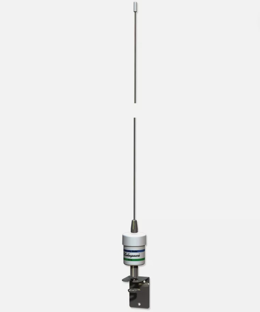 Fig. 3. Shakespeare 5215 VHF Sailboat Whip Antenna, image from Ebay
 Fig. 4. RG316 cable, image from AliExpress
 Fig. 5. New Generation RTL-2832 SDR USB dongle, image from Alibaba
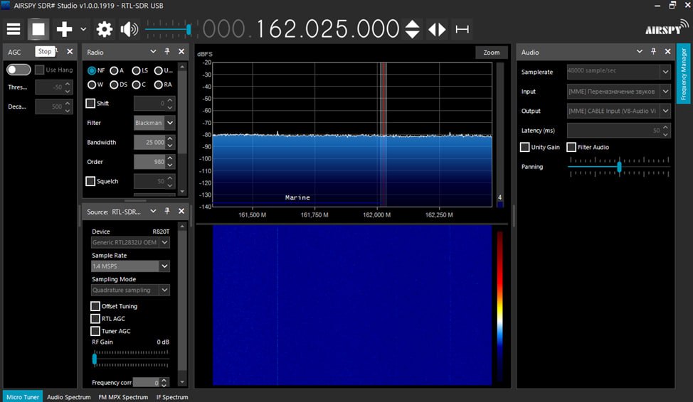 Fig. 6. General view of the SDR# program
 Fig. 7. Playback settings
 Fig. 8. Recording settings
 Fig. 9. Software bundle (signal reception – sound processing – signal decoding), generated by OpenAi
 Fig. 10. Map of the location of the AIS receiver relative to the port
 Fig. 11. Overview photo of the city along the signal reception path
 Fig. 12. Port cranes 1
 Fig. 13. Port cranes 2
 Fig. 14. Maersk Tukang and Maersk Conakry vessels in ShipPlotter.
 Fig. 15. Maersk Tukang vessel, GORADAR / SHIPINFO service page
 Fig. 16. Maersk Conakry vessel, GORADAR / SHIPINFO service page
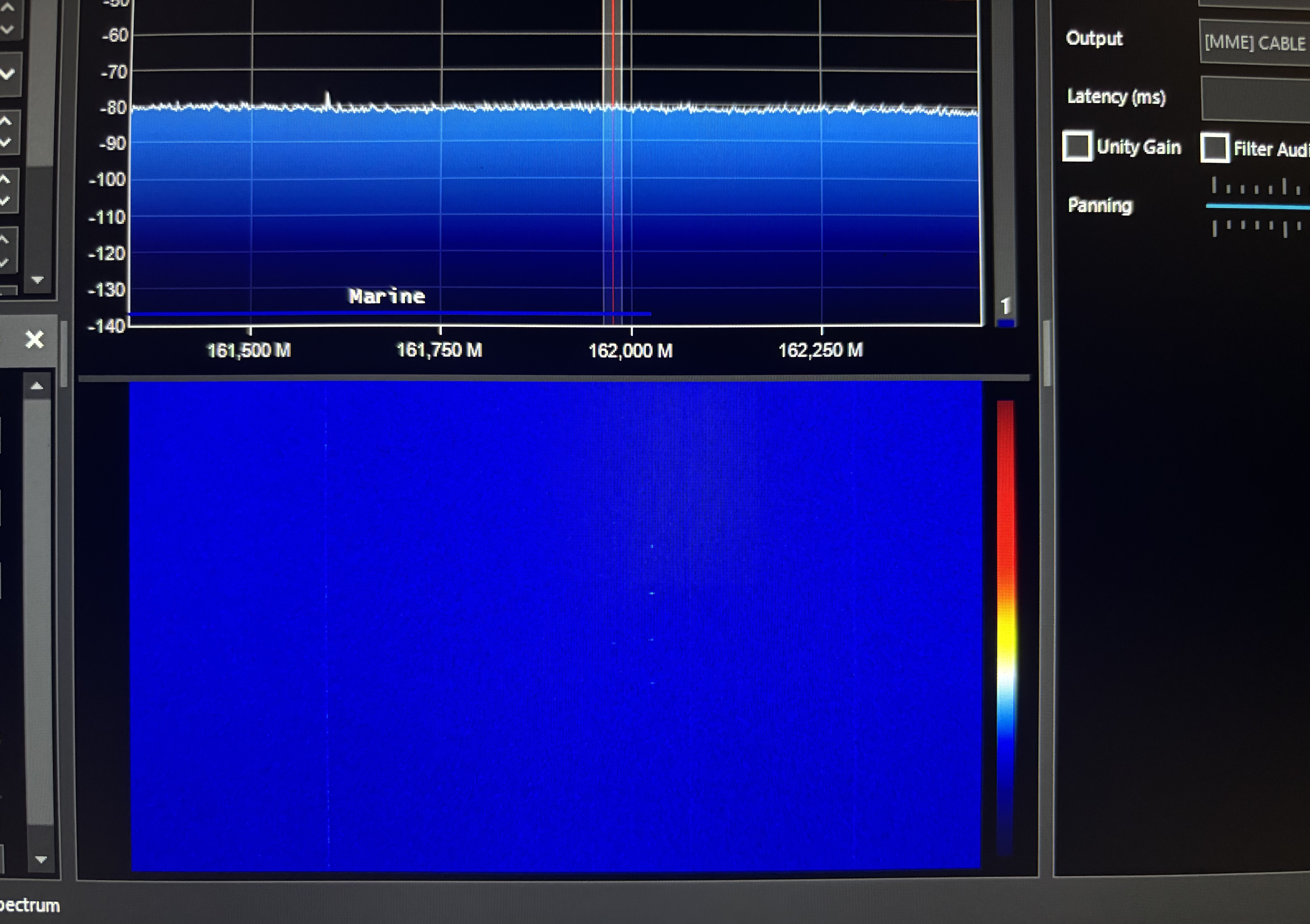 Fig. 17. AIS signals in SDR# program (horizontal dots at the bottom of the screen)
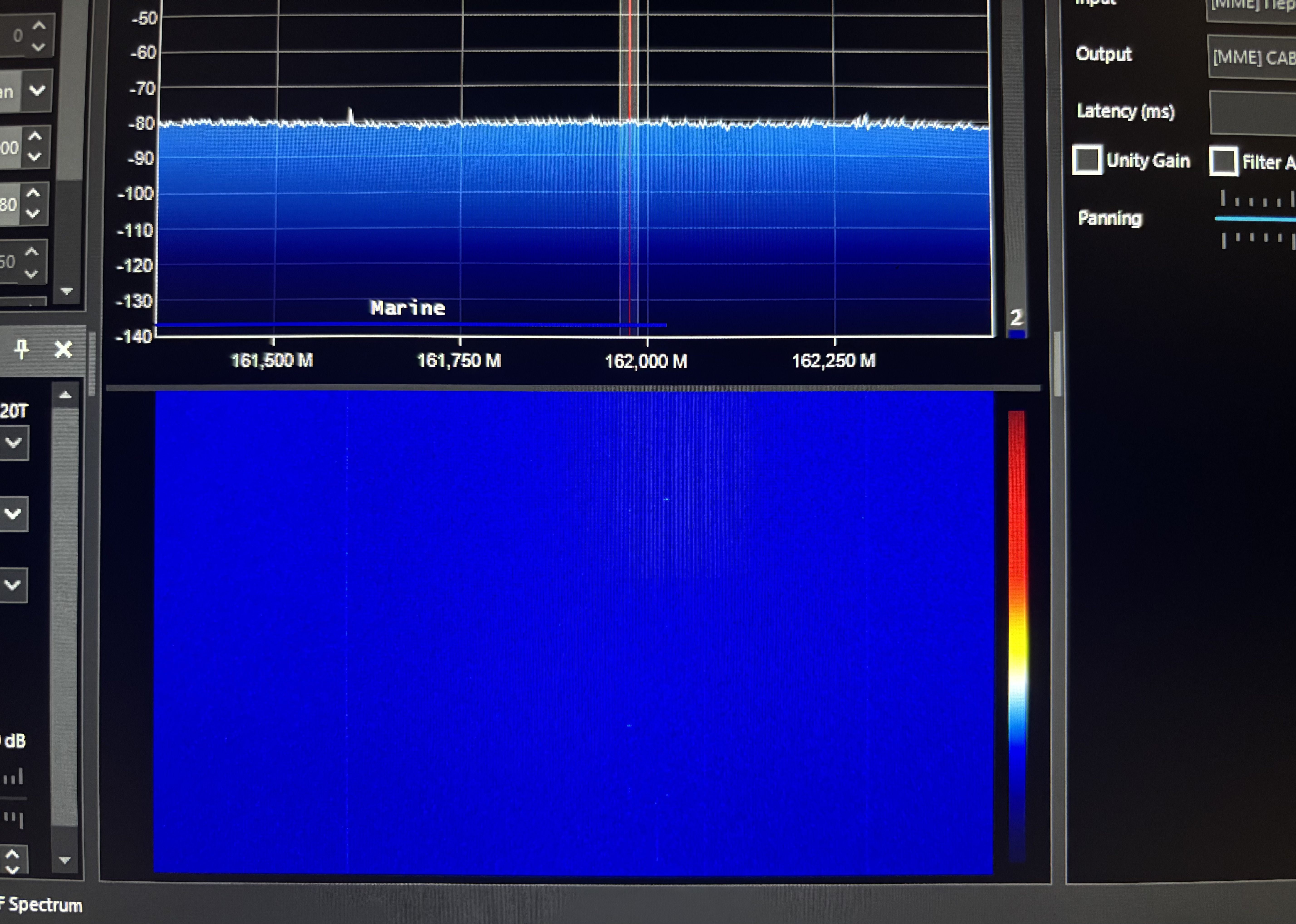 Fig. 18. AIS signals in SDR# program (horizontal dots at the bottom of the screen)
 Fig. 19. AIS signals in SDR# program (horizontal dots at the bottom of the screen)
 Fig. 20. Colombo port water area, screenshot from Google Earth